Hazard Controller
Overview
The HazardController acts as the primary pipeline interlock and control protection unit for a pipelined RV32I processor. It dynamically analyzes active instruction source registers against down-pipeline destination states to identify load-use data hazards and branch/jump control hazards, safely stalling or flushing stages to preserve execution integrity.
- Purpose in CPU: Coordinates pipeline state hazards by emitting control-flow overrides (
StallandFlush) when an instruction's required data isn't yet available for forwarding, or when a branch misprediction/jump changes the execution path. -
Role in datapath: Intersects the boundaries between the Fetch (IF), Decode (ID), and Execution (EX) pipeline registers to orchestrate synchronous pauses or instruction invalidations.
-
Source:
logisim/RiskVControl.circ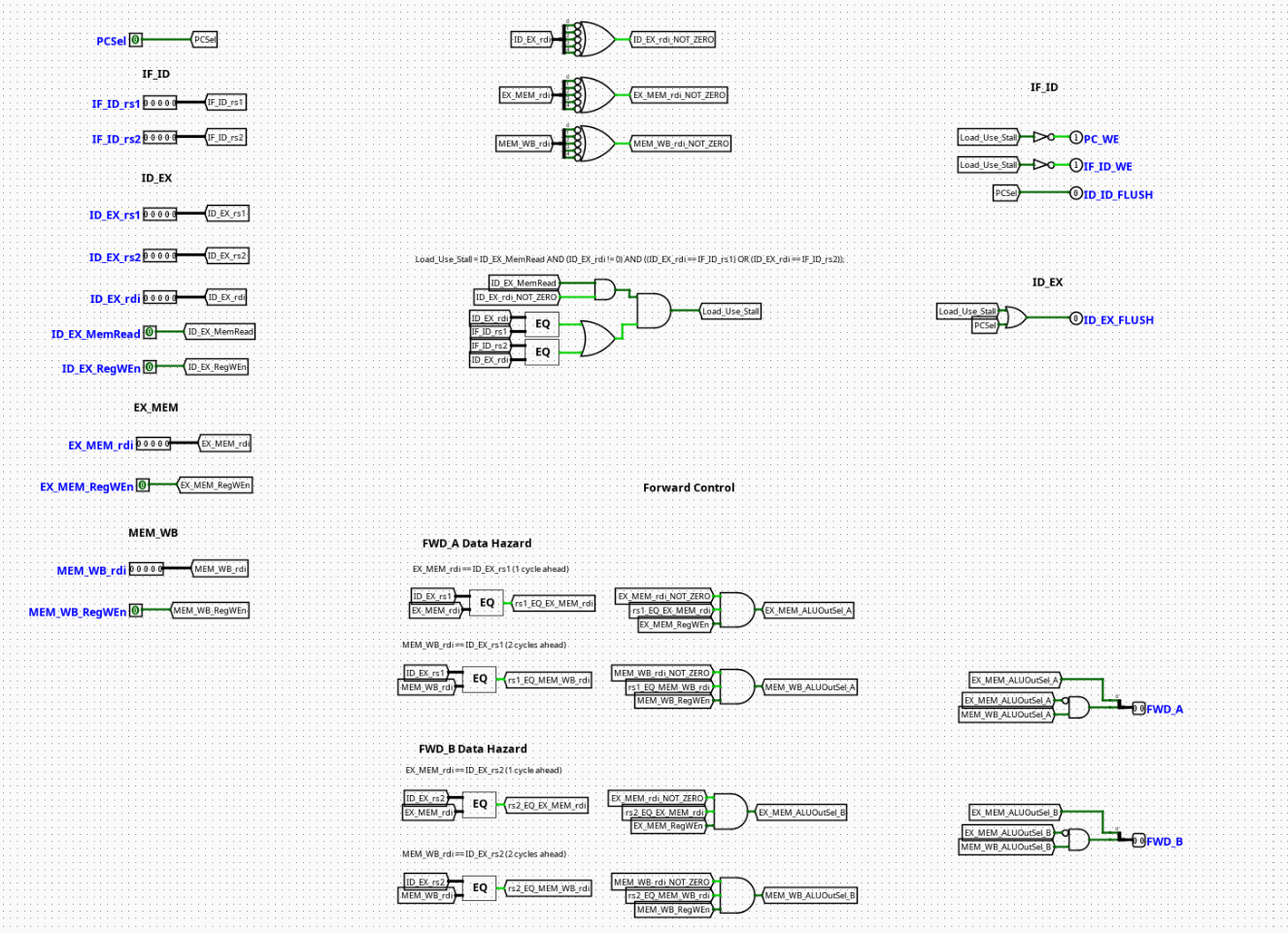
Interface
Inputs
| Signal | Width | Description |
|---|---|---|
ID_EX_MemRead |
1 bit | Active high indicator showing if the instruction currently executing in the EX stage is a memory load command (e.g., lw). |
ID_EX_rd |
5 bits | Destination register address of the instruction currently residing in the Execution (EX) stage. |
IF_ID_rs1 |
5 bits | Source register 1 address decoded from the raw instruction in the Instruction Decode (ID) stage. |
IF_ID_rs2 |
5 bits | Source register 2 address decoded from the raw instruction in the Instruction Decode (ID) stage. |
PCSrc |
1 bit | Control signal from the branch/jump execution logic indicating whether a control-flow deviation should be taken. |
Outputs
| Signal | Width | Description |
|---|---|---|
Stall |
1 bit | Active high interlock signal used to freeze the Program Counter (PC) register and the IF/ID pipeline latch. |
Flush |
1 bit | Active high clear signal used to invalidate stale instructions in the pipeline registers, transforming them into bubbles (NOPs). |
Output Logic (Core Definition)
Defines how operational hazards translate into structural control responses across the tracking networks.
Rule-based definition
1. Load-Use Data Hazard Detection (Stall Logic)
A load-use hazard occurs when an instruction in the Instruction Decode (ID) stage requires a source register that is currently being loaded from data memory by a preceding load instruction in the Execution (EX) stage. Because memory read data is not available until the end of the Memory (MEM) stage, forwarding alone cannot resolve this hazard, and a 1-cycle stall must be inserted.
- If \(\text{LoadUseHazard} == 1\) and \(\text{ID\_EX\_rd} \neq 0\):
Stall=1- Else:
Stall=0
2. Control Hazard Detection (Flush Logic)
A control hazard occurs when a conditional branch is taken or an unconditional jump executes, altering the sequential execution stream. Instructions that were speculatively fetched behind the branch/jump must be discarded.
- If
PCSrc=1: Flush=1(Clears the volatile pipeline stage contents to block illegal instruction execution tracking)- Else:
Flush=0
Internal Design
The module uses purely combinational logic circuits to evaluate condition vectors dynamically within the active clock phase.
- Structure: Purely combinational logic framework containing zero sequential elements, flip-flops, or discrete clock paths.
- Comparators: Utilizes 5-bit digital equality comparators to monitor matching intersections between the active target register field (
ID_EX_rd) and upstream decoded decoding registers (IF_ID_rs1/IF_ID_rs2). - Logic Gates: Standard primitive gates (
AND,OR) compile the hazard matches alongside the status state lineID_EX_MemReadto evaluate the load-use penalty. The control hazard signal passes through to theFlushoutput channel to instantly neutralize instruction steps.
Pipeline Interaction
- Pipeline stage involvement: Centrally targets the control signals driving the IF (Instruction Fetch) and ID (Instruction Decode) stage registers.
- Signal propagation across stages: Listens to decoded values within the ID stage boundary while simultaneously monitoring memory intent and target registers across the EX stage.
- Dependencies: Intersects with the global clock gating lines. When a
Stallgoes high, it typically commands the Program Counter (PC) and IF/ID pipeline registers to hold their current values, while generating a structuralNOPin the ID/EX register to clear space for the delayed operation.
Examples
Example 1: Load-Use Hazard Encountered
Inputs:
ID_EX_MemRead=1(Preceding instruction is a load, e.g.,lw x5, 0(x10))ID_EX_rd=0x05(Targeting destination registerx5)IF_ID_rs1=0x05(Succeeding instruction requiresx5, e.g.,add x2, x5, x6)PCSrc=0
Outputs:
Stall=1(Forces the processor to stall the current fetch/decode state for one cycle)Flush=0
Example 2: Branch Taken (Control Hazard)
Inputs:
ID_EX_MemRead=0PCSrc=1(Branch comparison evaluates to true; execution path diverts)
Outputs:
Stall=0Flush=1(Signals pipeline latches to discard speculatively fetched instructions on the next clock edge)
Limitations / Assumptions
- Assumes register zero (
x0) handling is cleanly isolated if the hardware allows it, preventing unnecessary structural stalls when an instruction targetsx0. - Does not manage deeper multi-cycle dependencies beyond immediate execution/decode phase boundaries; assumes separate structural units or standard forwarding handles standard ALU-to-ALU interactions.
- Relies on clean, hazard-free
PCSrccalculations from the execution block to avoid erroneous or oscillating flushing loops.
Implementation Notes
- Assembled cleanly using native Logisim
GatesandArithmeticcomparison modules. - Built without specialized black-box add-ons, ensuring cross-compatibility with standard Logisim-evolution distributions.
- Mapped with clean, descriptive localized
Tunnelsto minimize crossing wires and maximize clarity for troubleshooting and design review.