CacheController Component
Overview
The CacheController coordinates memory transactions between a RISC-V processor core and external main memory. It implements a 4-way set-associative blocking cache architecture containing 32 sets, with a line size of 8 words (32 bytes). The component automatically handles parallel way lookups, single-cycle hit execution, multi-cycle line-fill bursts upon a cache miss, and pseudo-LRU eviction updates.
- Purpose in CPU: Bridges the operational frequency gap between high-speed CPU registers and high-latency main memory, minimizing pipeline stalls by storing local blocks of recently accessed memory.
-
Role in Datapath: Intercepts the processor's memory access stage, inspecting read/write requests, stalling the pipeline on cache misses, and steering data buses to return words or commit byte-masked store instructions.
-
Source:
logisim/RiskVCache.circ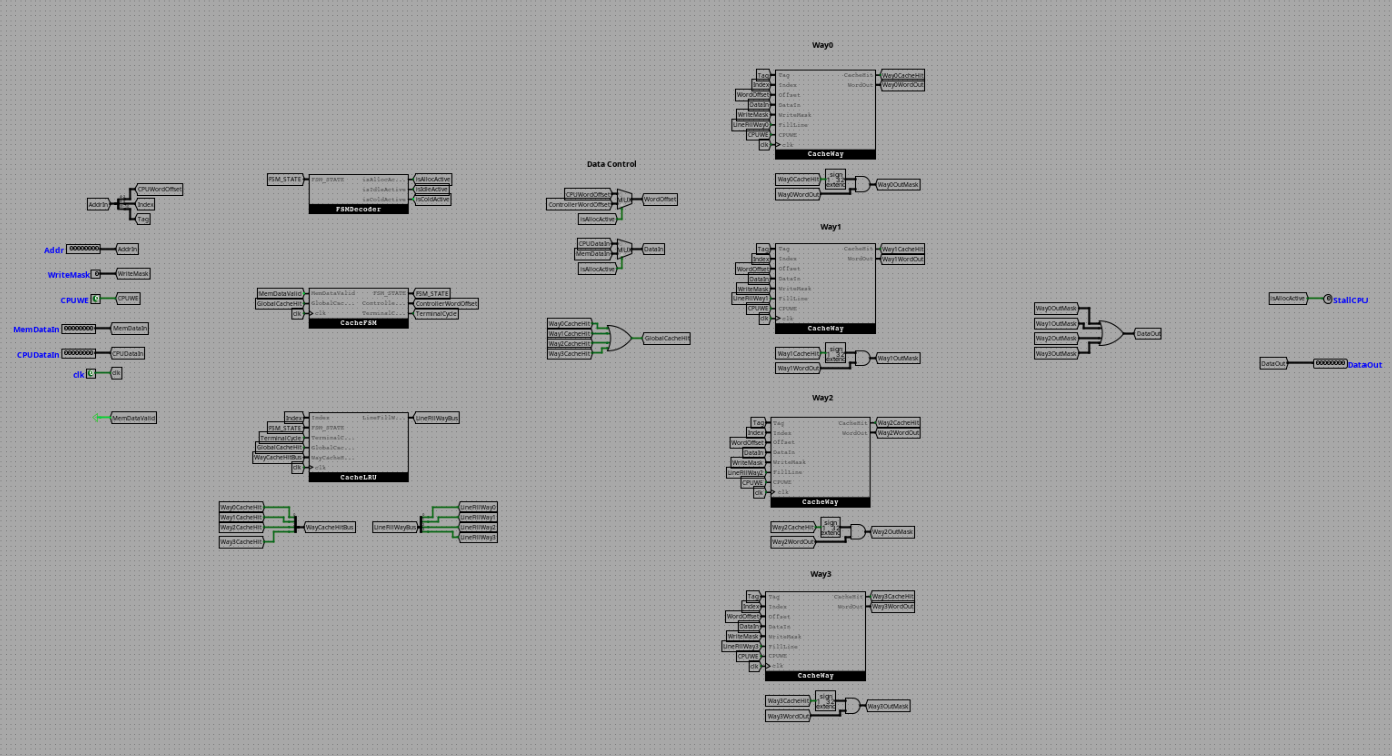
Interface
Inputs
| Signal | Width | Description |
|---|---|---|
CPU_Addr |
32 | Memory address issued by the processor core (Tag[31:10], Index[9:5], WordOffset[4:2], ByteOffset[1:0]) |
CPU_DataIn |
32 | 32-bit store data originating from processor registers |
CPUWE |
1 | Master write-enable strobe from the CPU indicating a store operation |
WriteMask |
4 | Byte-level write-enable mask bits supporting byte, halfword, or word stores |
MemReady |
1 | External memory interface flag verifying a valid word transmission during memory bursts |
MemDataIn |
32 | 32-bit word streaming from main memory during a cache line fill |
clk |
1 | System global clock signal |
rst |
1 | System synchronous reset line |
Outputs
| Signal | Width | Description |
|---|---|---|
CPU_DataOut |
32 | Filtered/aligned 32-bit data word returned to the processor pipeline |
CacheReady |
1 | Hardware status indicator used to stall (0) or clear (1) the CPU pipeline |
MemAddr |
32 | Address bus routed to external memory during line fills or writebacks |
MemRE |
1 | Memory Read Enable line asserted to initiate an external line-fill sequence |
MemWE |
1 | Memory Write Enable line asserted during dirty line evictions |
Output Logic (Core Definition)
Rule-based definition
- When
FSM_STATE == STATE_COLD(Power-on Reset): - Continuous evaluation occurs. If an immediate cache match is found, route
NEW_FSM_STATE = STATE_IDLE. If a miss is registered, routeNEW_FSM_STATE = STATE_ALLOC. -
FSM_WEis forced high to exit the cold state on the first clock edge. -
When
FSM_STATE == STATE_IDLE: CacheReady = GlobalCacheHit. IfGlobalCacheHit == 1, the processor proceeds at full speed. IfGlobalCacheHit == 0, the CPU pipeline stalls.DataCtl = 0, forcing internal cache slots to acceptCPU_DataInand index words usingCPU_Addr[4:2].- If
GlobalCacheHit == 0, a transition is flagged:SignExtIdleToAloc = 1, drivingNEW_FSM_STATE = STATE_ALLOCand updating the FSM register. -
If
GlobalCacheHit == 1, the tree re-encoder triggersLRU_WE = 1to mark the hit way as Most Recently Used (MRU). -
When
FSM_STATE == STATE_ALLOC: CacheReady = 0is hardwired to freeze the processor pipeline during the block acquisition.DataCtl = 1, switching cache data paths to acceptMemDataInand indexing word lanes using the internalControllerWordOffset.MemRE = 1, keeping the external memory read request line active.Counter_Inc = MemReady, incrementing the burst counter from0to7every time memory asserts a data-valid flag.- When
ControllerWordOffset == 7andMemReady == 1, the transition triggers:SignExtAlocToIdle = 1, committing tag metadata, setting the line valid bit, updating the LRU array, and returning toSTATE_IDLE.
Boolean expressions
isColdActive = (FSM_STATE == 0)
isIdleActive = (FSM_STATE == 1)
isAllocActive = (FSM_STATE == 2)

SignExtColdToIdle = GlobalCacheHit AND isColdActive
SignExtColdToAloc = NOT(GlobalCacheHit) AND isColdActive
SignExtIdleToAloc = NOT(GlobalCacheHit) AND isIdleActive
SignExtAlocToIdle = (ControllerWordOffset == 7) AND MemReady AND isAllocActive

FSM_WE = SignExtColdToIdle OR SignExtColdToAloc OR SignExtIdleToAloc OR SignExtAlocToIdle

STATE_CHANGE = (SignExtIdleToAloc AND STATE_ALLOC) OR
               (SignExtAlocToIdle AND STATE_IDLE)  OR
               (SignExtColdToIdle AND STATE_IDLE)  OR
               (SignExtColdToAloc AND STATE_ALLOC)

Counter_Reset = isColdActive OR isIdleActive
Counter_Inc   = isAllocActive AND MemReady

DataCtl = isAllocActive
Internal Design
The CacheController macro-component orchestrates the interface through structured combinational selection networks and synchronous tracking tables:
- FSM State Core: Manages the active state using a 2-bit clock-gated state register. Because it uses conditional
WElogic derived from transition equations, it implements next-state logic without the use of structural feedback multiplexers on its data port. - Data Path Multiplexing Architecture: Incorporates wide multiplexers handling the distribution of data and word addresses. The selection lines are driven by the
DataCtlsignal, dynamically re-routing access lanes away from the CPU toward the external memory bus during a block refill. - Hit Detection Consolidation: Takes the 4 individual
CacheHit_Nlines from the storage ways, feeding them into a 4-input OR gate to establishGlobalCacheHit. It concurrently drives a 4-to-1 data multiplexer to extract the correct 32-bit word from the matching cache line.
Operation
- CPU Request Phase:
CPU_Addrand control lines settle. The 5-bit index (CPU_Addr[9:5]) isolates a set simultaneously within all four ways and the Pseudo-LRU module. - Tag Matching Evaluation: In
STATE_IDLE, the four ways output their stored tags combinationally. The tag comparators evaluate these lines againstCPU_Addr[31:10]. If a valid hit occurs, data is passed toCPU_DataOutwithin the same cycle, and the LRU tree updates. - Refill Sequence Initiation: On a cache miss, the state register locks into
STATE_ALLOCon the next clock edge.CacheReadydrops low, stalling the processor. The Pseudo-LRU matrix evaluates the tree switches and identifies the victim way, asserting its specificLineFillWay_Nwire. - Burst Transfer Execution: As main memory asserts
MemReady, words0through7flow sequentially into the targeted data lanes of the victim way. The internal burst counter steps forward tracking the block fill. - Metadata Commitment & Resume: Upon reaching the final word (
ControllerWordOffset == 7), the controller closes the data lane, flushes the new tag into the Way's Tag RAM, sets the valid bit high, updates the LRU index status, and returns toSTATE_IDLEto fulfill the CPU request.
Limitations / Assumptions
- Blocking Operation Constancy: The cache controller handles requests strictly in a blocking layout. The CPU core is entirely stalled during line fills; no non-blocking lookups or hit-under-miss tracking can occur.
- Write-Through Protocol Dependence: Assumes write transactions are written through to external data buffers concurrently if cache modifications alter lines, maintaining consistent core state alignments.
- Ideal Memory Boundary: Assumes external memory correctly responds with sequential burst data matching lower offset fields
000to111linearly during an allocation phase.
Implementation Notes (Logisim)
- Assembled exclusively using native Logisim primitives, guaranteeing full compatibility without external macro dependencies.
- Employs an asynchronous read layout across Tag and Valid RAM grids to ensure lookup hits or misses evaluate combinationally inside a single execution phase.
- Buses use clean split networks and tri-state buffer banks where necessary to eliminate floating wire configurations during line-switching processes.
Submodules
1. CacheWay
The CacheWay submodule provides the primary storage fabric for the cache line arrays, mapping 32 distinct rows (sets). Each slot entry manages a 1-bit validation block, a 22-bit tag field, and an 8-word data line array.
- Internal Data Grid: Comprises 8 discrete RAM nodes configured as \(32 \times 32\text{-bit}\) blocks. This structure enables individual word lane modifications via a internal 3-to-8 demultiplexer driven by the active
WordOffset. - Gated Write Architecture: The demultiplexer activation line maps to: $\(\text{Demux\_Enable} = (\text{CacheHit} \cdot \text{CPUWE}) + \text{LineFill}\)$ This allows single-word CPU stores to alter individual data elements on a cache hit, or permits the FSM controller to sequentially stream words 0–7 during a burst block allocation phase.
- Metadata Framing: Tag memory allocations and row validation entries are locked until the termination cycle of an allocation block: $\(\text{Metadata\_WE} = \text{LineFill} \cdot (\text{WordOffset} == 7)\)$ This gates updates until the full line is securely fetched, preventing tag corruption mid-burst.
2. Pseudo-LRU Eviction Router
Tracks block access history across the 32 cache sets using a binary tree tracking system (\(32 \times 3\text{-bit}\) RAM). It maps three directional tracking bits (B0 root, B1 left child, B2 right child) to isolate eviction targets.
- Section 1: Storage Layer: Contains the \(32 \times 3\text{-bit}\) memory core driven by the 5-bit set index.
- Section 2: Eviction Decoder: Translates tree directions into a 4-bit one-hot vector during miss processing:
$\(\text{ActiveWay0} = \overline{B_0} \cdot \overline{B_1}, \quad \text{ActiveWay1} = \overline{B_0} \cdot B_1, \quad \text{ActiveWay2} = B_0 \cdot \overline{B_2}, \quad \text{ActiveWay3} = B_0 \cdot B_2\)$
These vectors are gated with
isAllocActiveto emitLineFillWay_Nsignals to the target cache slots. - Section 3 & 4: Re-Encoder Feedback: When an index is accessed (via hit or fill allocation), a tracking crossbar evaluates the active block path. It recalculates the updated tree configurations to point completely away from the active way, marking it Most Recently Used (MRU). Unvisited tree branches are mirrored forward directly from the RAM read lines to prevent state corruption: $\(\text{Next\_}B_0 = \text{AccessWay0} + \text{AccessWay1}\)$ $\(\text{Next\_}B_1 = \text{AccessWay0} + (\overline{\text{AccessWay1}} \cdot B_1)\)$ $\(\text{Next\_}B_2 = \text{AccessWay2} + (\overline{\text{AccessWay3}} \cdot B_2)\)$
- Write Control: Commits values on the clock edge via the gated write strobe: $\(\text{LRU\_WE} = (\text{isIdleActive} \cdot \text{GlobalCacheHit}) + (\text{isAllocActive} \cdot (\text{ControllerWordOffset} == 7))\)$