EX | MEM Pipeline Register
EX_MEM
Overview
The EX_MEM component serves as the localized pipeline stage boundary register isolating the Execution (EX) stage from the Memory Access (MEM) stage of a pipelined RV32I processor. It synchronizes and preserves control paths, computation results, and store data configurations as instructions pass across the execution boundary.
- Purpose in CPU: Buffers execution metrics, destination register pointers, and memory control states across clock cycles to prevent downstream data collisions while preceding instructions enter the execution stage.
-
Role in datapath: Latches output lines from the ALU and forwarding multiplexers, holding them stable for a full cycle before presenting them to the Data Memory (DMem) interface and the subsequent writeback selectors.
-
Source:
logisim/RiskVPipelineRegs.circ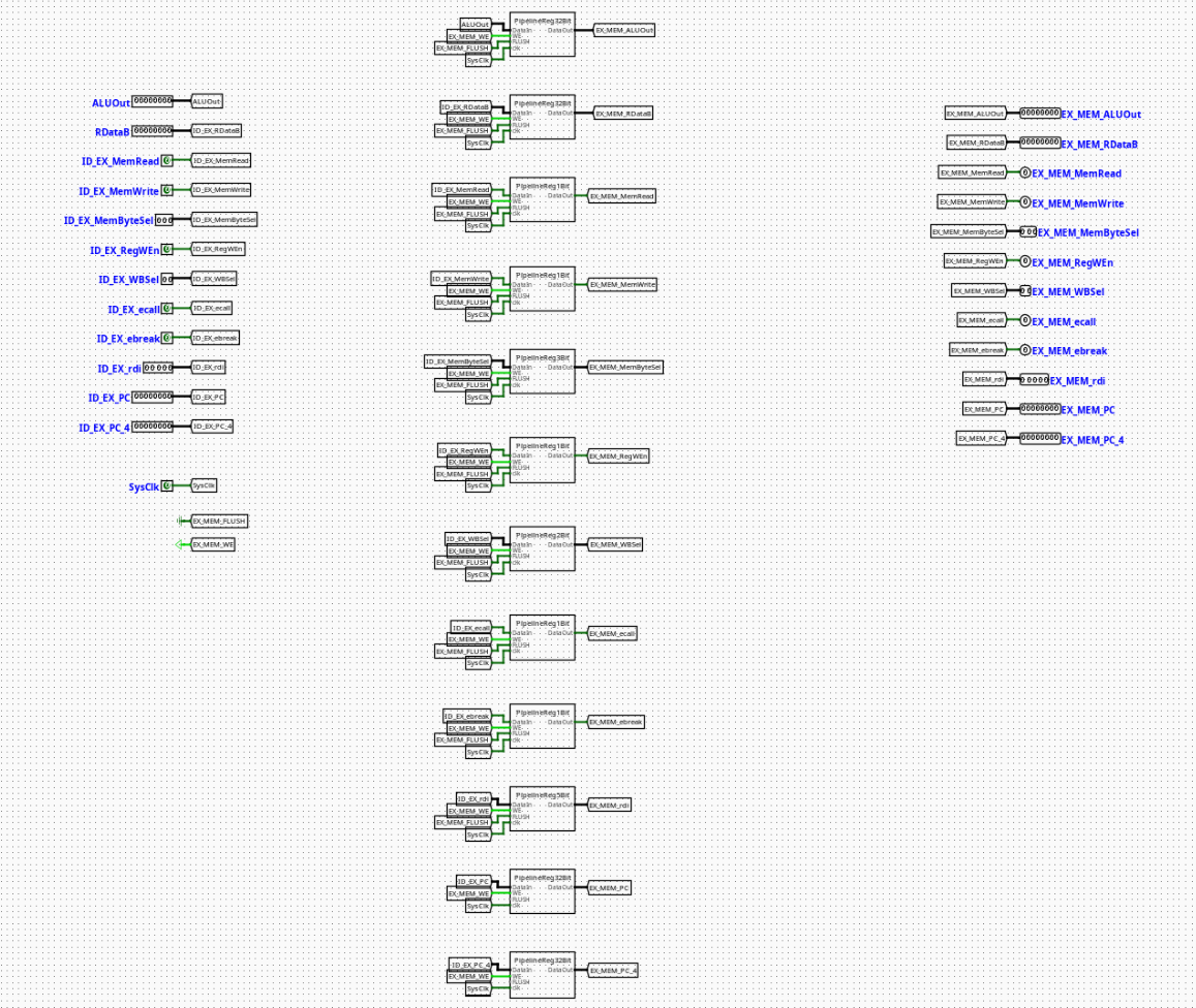
Interface
Inputs
| Signal | Width | Description |
|---|---|---|
SysClk |
1 bit | Master system clock line driving all internal edge-triggered sub-registers. |
EX_MEM_WE |
1 bit | Active-high write enable control bit. When deasserted (0), updates are frozen to enforce a pipeline stall. |
EX_MEM_FLUSH |
1 bit | Active-high synchronous flush vector. Overrides incoming tracks to inject a pipeline bubble. |
MemRead |
1 bit | Memory read strobe flag required for down-line load operational gating. |
MemWrite |
1 bit | Memory write strobe flag required for data preservation operations. |
MemByteSel |
3 bits | Encoded format selector classifying memory dimensions (lb, lh, lw, lbu, lhu). |
RegWEn |
1 bit | Register write enable signal intended for the eventual Writeback destination. |
WBSel |
2 bits | Multi-channel multiplexer selection path index tracking the origin of the writeback data payload. |
ecall |
1 bit | Environment call instruction exception indicator. |
ebreak |
1 bit | Environment break instruction exception indicator. |
rdi |
5 bits | 5-bit target destination register address tracking index (rd). |
ALURes |
32 bits | Raw computational result or calculated memory address from the ALU core. |
MemWData |
32 bits | Forwarded source register data payload ready for data memory write execution. |
Outputs
| Signal | Width | Description |
|---|---|---|
EX_MEM_MemRead |
1 bit | Synchronized load-activation indicator tracking memory execution blocks. |
EX_MEM_MemWrite |
1 bit | Synchronized store-activation indicator tracking memory execution blocks. |
EX_MEM_MemByteSel |
3 bits | Latched instruction width modifier parsing data memory access boundaries. |
EX_MEM_RegWEn |
1 bit | Forwarded writeback register destination update tracking parameter. |
EX_MEM_WBSel |
2 bits | Forwarded selection tracking bits for terminal writeback sourcing. |
EX_MEM_ecall |
1 bit | Latched exception indicator signaling execution traps downstream. |
EX_MEM_ebreak |
1 bit | Latched exception indicator signaling hardware diagnostic steps downstream. |
EX_MEM_rdi |
5 bits | Latched structural index field specifying the target destination register. |
EX_MEM_ALURes |
32 bits | Latched data memory address index or bypass operand passed to downstream stages. |
EX_MEM_MemWData |
32 bits | Latched store data payload presented to the data memory write ports. |
Output Logic (Core Definition)
The evaluation of state variables occurs synchronously over each master system clock transition.
Rule-based definition
- Synchronous Flush Mode:
-
If
EX_MEM_FLUSH==1→ All output data channels, destination register indices, and control flags are forced synchronously to0. This effectively invalidates downstream instructions by turning them into non-operational bubbles. -
Standard Gated Latch Mode:
-
If
EX_MEM_FLUSH==0andEX_MEM_WE==1→ Outputs update cleanly to match the active incoming datapath fields (EX_MEM_X=X). -
Freeze / Hold Mode:
- If
EX_MEM_FLUSH==0andEX_MEM_WE==0→ The component locks its current state registers, ignoring updates on the input buses to hold the memory-stage context constant until hazards clear.
Internal Design
The circuit architecture segregates data bit-planes by nesting uniform register blocks inside dedicated submodules mapped to specific widths.
- Combinational vs Sequential Structure: The underlying state containment is sequential and edge-triggered. The conditional clear loops, input-intercept multiplexers, and write-enable distribution systems are completely combinational.
- Subcircuits Used:
PipelineReg1Bit(Encapsulates a single-bit register with built-in flush multiplexing for basic flags)PipelineReg2Bit(Manages the 2-bitWBSelsignal track)PipelineReg3Bit(Manages the 3-bitMemByteSelconfiguration track)PipelineReg5Bit(Manages the 5-bitrditarget register index)-
PipelineReg32Bit(Buffers the wide 32-bitALUResandMemWDatabusses) -
Gating Framework: Each bit-plane width variant utilizes an input-side multiplexing layout. Asserting
EX_MEM_FLUSHchanges the selection on internal 2-to-1 multiplexers placed right before the register input pins, diverting the storage targets away from live data and into constant zero blocks. Local control paths distributeEX_MEM_WE,EX_MEM_FLUSH, andSysClkin parallel across all internal blocks using unified label tunnels.
Operation
Step-by-step behavior:
- Signals Present: Computation results from the ALU, forwarded register data, and execution control maps settle on the input pins.
- Control Evaluation: Hazard controller states establish the conditions of the
EX_MEM_WEandEX_MEM_FLUSHtracking lines. - Synchronized Latching: On the positive edge transition of
SysClk, internal registers process the active controls—either latching new inputs, locking current values, or wiping fields to zero if flushed. - Stable Output Presentation: Refreshed signals update at the output ports, initializing clean address indexes, store values, and control parameters for the Data Memory module.
Pipeline Interaction
- Pipeline stage involvement: Links the EX (Execution) stage workspace directly with the MEM (Memory Access) hardware framework.
- Signal propagation across stages: Packs ALU results and store data to pass them smoothly to the data memory infrastructure, isolating the memory stage from combinational fluctuations in the execution stage.
- Dependencies: Responds directly to central control units. During system exceptions or down-line memory interlocks, this register can be stalled or flushed to retain datapath synchronization.
Examples
Example: Passing a Store Word Instruction (sw x5, 8(x10))
Inputs:
EX_MEM_WE=1,EX_MEM_FLUSH=0MemWrite=1,MemRead=0,MemByteSel=010(Word size format)ALURes=0x10000008(Target destination memory address calculated by ALU)MemWData=0xABCDEF12(Payload from registerx5)rdi=0x00(Destination register field is ignored during standard stores)
Outputs / State Changes:
- On Next Clock Edge: Internal registers capture the active parameters.
EX_MEM_ALUResbecomes0x10000008(Addresses the target word in memory).EX_MEM_MemWDatabecomes0xABCDEF12(Presents write payload data).EX_MEM_MemWritetransitions high to initiate the synchronized write sequence in DMem.
Limitations / Assumptions
- Assumes a well-timed, non-skewed system clock layout (
SysClk) to prevent propagation racing between parallel bit-width slices. - Does not contain independent validation logic for addresses or data fields; assumes upstream exception handling manages out-of-bounds metrics.
- Assumes the external control engine prevents conflicting simultaneous assertions of write-enable and flush states.
Implementation Notes
- Engineered using standard primitives from Logisim-evolution's
Memory(Registers),Plexers(Multiplexers), andWiring(Splitters/Tunnels) toolsets. - Cleanly compartmentalizes wiring by allocating custom sub-register blocks for specific bit widths.
- Employs local label tunnels to systematically route control parameters (
SysClk,EX_MEM_WE,EX_MEM_FLUSH), eliminating crossed lines and ensuring a clean visual structure.