Immediate Generator
Overview
The ImmediateGenerator (ImmGen) is a critical combinatorial component within the Instruction Decode (ID) stage of an RV32I pipelined processor. Its sole responsibility is to extract, reorder, and sign-extend immediate bit fields embedded within various RISC-V instruction formats into a standardized 32-bit two's complement integer value.
- Purpose in CPU: Reconstructs broken or scattered immediate constants directly from the raw 32-bit machine code instruction field to supply constants for arithmetic calculations, memory offsets, and branch/jump targets.
-
Role in datapath: Decodes raw instruction bits coming out of the Instruction Fetch (IF) pipeline register and passes a unified 32-bit scalar output directly down to the ALU operand multiplexers and target program counter calculation blocks.
-
Source:
logisim/RiskVControl.circ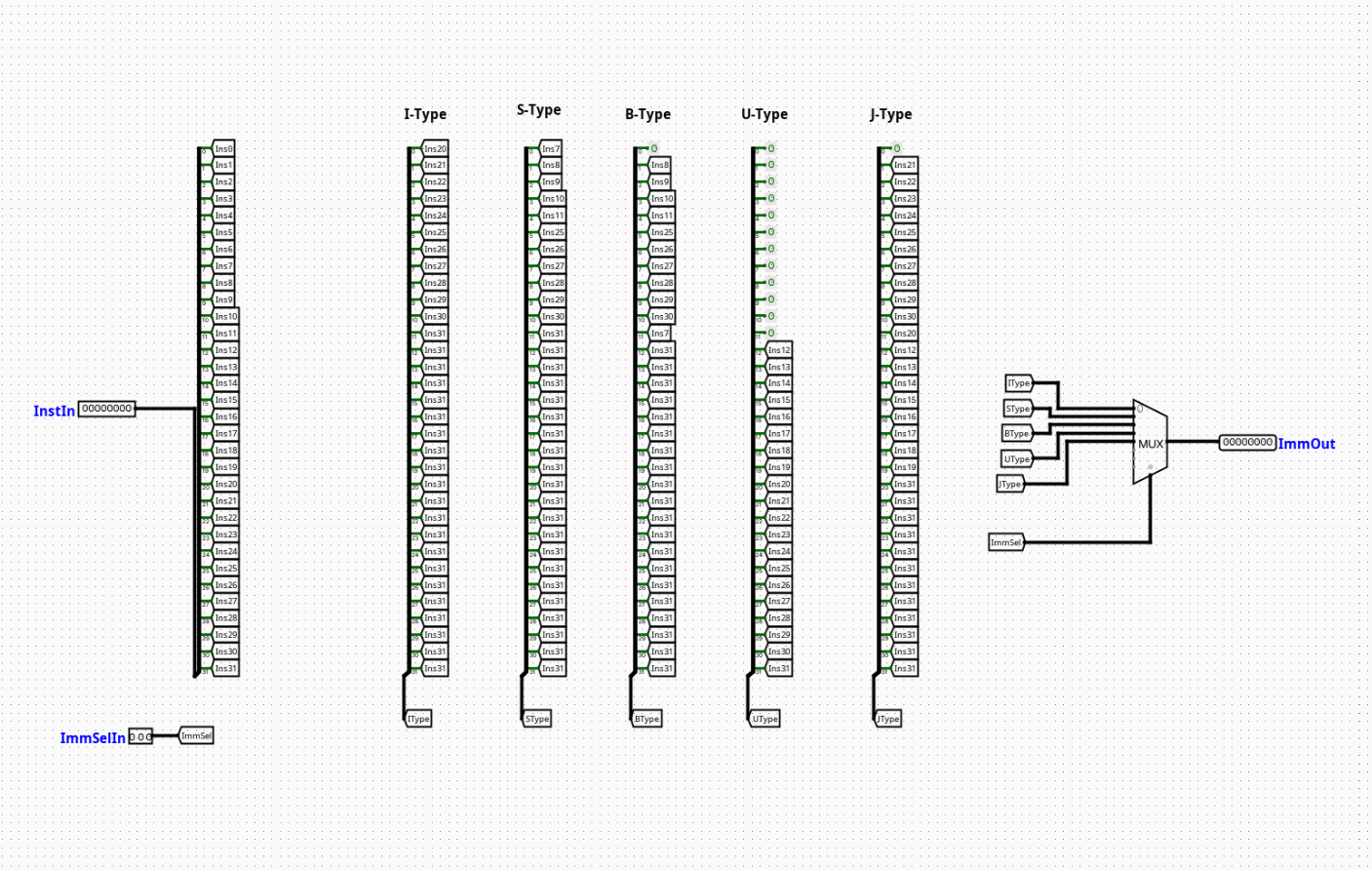
Interface
Inputs
| Signal | Width | Description |
|---|---|---|
Instruction |
32 bits | Raw 32-bit machine language instruction fetched from instruction memory. |
ImmSel |
3 bits | Structural control routing signal dictating which immediate format variant (I, S, B, U, J) to parse. |
Outputs
| Signal | Width | Description |
|---|---|---|
Immediate |
32 bits | Formatted, re-assembled, and fully sign-extended 32-bit constant value ready for execution. |
Output Logic (Core Definition)
The extraction behavior of the unit is driven entirely by the ImmSel configuration line. It maps specific slices of the 32-bit raw instruction input array into an aligned 32-bit wide internal structure.
Rule-based definition
The following table outlines how the 32-bit immediate string is assembled based on the active ImmSel parameter:
ImmSel Value |
Format Type | Immediate Bit Mapping Layout (From MSB to LSB) |
|---|---|---|
000 |
I-Type | {{20{Instruction[31]}}, Instruction[31:20]} |
001 |
S-Type | {{20{Instruction[31]}}, Instruction[31:25], Instruction[11:7]} |
010 |
B-Type | {{19{Instruction[31]}}, Instruction[31], Instruction[7], Instruction[30:25], Instruction[11:8], 1'b0} |
011 |
U-Type | {Instruction[31:12], 12'b0} |
100 |
J-Type | {{11{Instruction[31]}}, Instruction[31], Instruction[19:12], Instruction[20], Instruction[30:21], 1'b0} |
| Others | Default | Outputs 0x00000000 (or treated as unmapped error states) |
Internal Design
The circuit is purely combinational, containing no state tracking or registers, relying instead on bit-splitting arrays and dynamic multiplexer routing networks.
- Structure: Asynchronous combinational topology optimized for low signal-settlement latency within the decoding lifecycle.
- Bit Slicing & Merging: Employs standard Logisim
Splitterblocks to isolate discrete segment offsets from the 32-bitInstructionbundle. These disjoint bit groups are combined alongside duplicate sign bits using output bit reconstruction splitters. - Sign Extension Mechanics: Replicates the native instruction sign-bit position (
Instruction[31]) across higher-order positions using the fan-out properties of wire splitting nodes to achieve automated two's complement alignment. - Output Multiplexing: Features a single 32-bit width 8-to-1 Multiplexer (
Multiplexerconfigured with a 3-bit selection bus driven byImmSel) to route the correctly reconstructed format out to theImmediatepin.
Pipeline Interaction
- Pipeline stage involvement: Sits entirely inside the ID (Instruction Decode) stage of the processing track.
- Signal propagation across stages: Operates immediately downstream of the IF/ID pipeline register boundary, stabilizing its output before the next clock edge latches the values into the ID/EX pipeline buffer.
- Dependencies: Acts as a fundamental slave device to the main CPU Control Unit, which must supply the correct matching
ImmSelcode based on the opcode field of the incoming instruction.
Examples
Example 1: I-Type Extraction (e.g., addi x1, x2, -4)
- Input Instruction:
0xFFC10093(Instruction[31]=1) - Control Vector:
ImmSel=000 - Internal Mechanics: Extracts
Instruction[31:20]which equals0xFFC. Replicates bit 31 twenty times (0xFFFFF). - Output Immediate:
0xFFFFFFFC(Decimal-4)
Example 2: U-Type Extraction (e.g., lui x1, 0x12345)
- Input Instruction:
0x123450B7 - Control Vector:
ImmSel=011 - Internal Mechanics: Extracts
Instruction[31:12](0x12345) and appends 12 low-order trailing zero bits (0x000). - Output Immediate:
0x12345000
Limitations / Assumptions
- Assumes that byte-alignment, instruction fetching, and operational bounds have already been fully verified by upstream logic elements.
- Implicitly handles the unaligned bit configurations characteristic of standard RISC-V specifications (such as the scrambled bit indexing in B and J types designed to optimize fan-out configurations in physical hardware layouts).
- The low-order bit 0 for both B-Type and J-Type output tracks is tied explicitly to a hardware ground constant (
0), enforcing the required 2-byte instruction alignment standard for branch offsets.
Implementation Notes
- Built cleanly out of default
Wiring(Splitters, Tunnels) andPlexers(Multiplexers) logic blocks from the standard Logisim library suite. - Uses explicit label naming structures inside all tracking tunnels to maintain clarity and easily isolate specific bit groupings during testing.
- No clock dependencies or complex external functional libraries are imported.